


All Products
-
PLC Spare Parts
-
Bently Nevada Parts
-
ABB Module
-
ICS Triplex PLC
-
General Electric PLC
-
Triconex DCS
-
Honeywell Spare Parts
-
Woodward Module
-
Emerson Epro
-
Allen Bradley Modules
-
Emerson Delta V DCS
-
Schneider Electric Parts
-
Foxboro Parts
-
Westinghouse Ovation
-
Yokogawa Module
-
Bachmann Module
-
Hima PLC
-
Siemens Module
-
BR Module
-
DCS Spare Parts
-
MEGT VBM
-
Venable Instruments
-
 RahmatOur best supplier and friend Brown Luo,Thanks for her considerate service! We are honor cooperate with such a good company!
 -
 Linda VelichovaWe coopetate with Sumset International Trading Co., Limited company many years.They are our good partner and always offer best price and kind service!
 -
 Mohammed KhanSumset International Trading Co., Limited company is a reliable partner,we import goods from it. Reciving good quality products and timely service.It will be our long time cooperator!
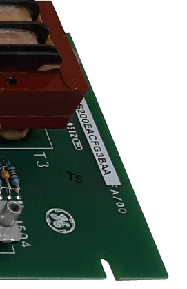
IS200EACFG3BAA Exciter AC Feedback Card

Product Details
| Brand | GE | Model | IS200EACFG3BAA |
|---|---|---|---|
| Conditon | In Stock | Original | USA |
| Highlight | IS200EACFG3BAA AC Feedback Card,Exciter AC Feedback Card |
||
Product Description
Product: IS200EACFG3BAA Exciter AC Feedback Card
Description
IS200EACFG3BAA is an Exciter AC Feedback Card developed by GE. It is a part of the EX2100 control system. The Exciter AC Feedback board is responsible for measuring the exciter Permanent Magnet Generator (PMG) AC supply voltage and current. The EACF (Exciter AC Feedback) board is situated within the exciter auxiliary cabinet.
Exciter Voltage Measurement
- G1 Version: This version supports a single three-phase input voltage within the nominal range of up to 480 V rms with a tolerance of +20% at either 50 or 60 Hz.
- G2 Version: The G2 version is designed to handle a single three-phase input voltage within the nominal range of up to 1000 V rms with a tolerance of +20% at either 50 or 60 Hz.
- Both versions of the board are equipped with potential transformers that supply a nominal output voltage of 1.6 V rms from their secondary outputs. Additionally, air core current transformers are employed, providing a nominal secondary output voltage ranging from 0 to 0.8 V rms at either 50 or 60 Hz.
Installation
- Preparation: Open the auxiliary cabinet door and ensure all electrical circuits are tested to confirm that power is off before proceeding.
- Disconnecting Cables: Carefully disconnect all cables from the board, ensuring adherence to the following steps-
- Verify that all cables are labeled with the correct connector name, as marked on the board, to simplify reconnection later.
- For voltage inputs, disconnect the wiring from screw connectors TB1, TB2, and TB3.
- For the coil inputs, disconnect the wiring at TB4.
- Handling Mounting Hardware: Exercise caution to avoid dropping any mounting hardware into the equipment, as this could lead to equipment damage or personal injury when power is reapplied.
- Removing the Board: Remove the three screws that secure the board to the mounting, and carefully detach the board from its position.
- Installing New Board: Orient the new board in the same position as the one removed, and securely install it onto the standoffs using the three screws removed in the previous step.
- Reconnecting Cables and Wires: Reconnect all cables and wires to the new board, ensuring that they are properly seated and connected as labeled. This step helps maintain proper functionality and connectivity.
- Finalization: Once all connections are verified and secured, close the auxiliary cabinet door to complete the replacement process. This ensures the integrity and safety of the system.
Recommended Products
| IS200ERDDH1ABA | IS200ERIOH1AAA |
| IS200EROCH1ABB | IS200ESELH2A |
| IS200ESELH1AAA | IS200EXAMG1AAB |
| IS200EXHSG3AEC | IS200FHVBG1ABA |
| IS200GGXDG1ABB | IS200GGXIG1AFE |
| IS200HFPAG1ADC | IS200HFPAG2ADC |
Pictures
![]()
Recommended Products